Building TK-Pie by Victor Trucco
- gozdnijezek
- Feb 26, 2022
- 6 min read
Updated: Oct 12, 2023
My friend and I built TK-Pie for Spectrum ZX 48k, a home computer from 1983, which is an edge connection add-on that enables you to connect your Spectrum to a modern HDMI TV/monitor. This is a quick instruction that will hopefully help you build your own.

How it works?
The TK-Pie watches the video memory addresses in Spectrum RAM (memory address &4000 onward) and uses raspberry pi and some clever software to generate an image that is than displayed through raspberry pi HDMI output. More on Spectrum video memory can be found here.
Building it
First of all, all of the needed resources can be found in Victors GitLab here:
Victor Trucco / TK-Pie
A baremetal OS to integrate Raspberry Pi with ZX Spectrum and other clones.
gitlab.com
Source description
Once you download the project and unzip it, you’ll get the following files:

CPLD contains the source and files to program the CPLD (main chip),
gerbers contain the PCB design ,
photos contains the photos of the prototypes,
PI_OS is the raspberryPi firmware,
PI_SD contains the source code for TK-Pie, as well as the precompiled version for Pi-Zero, if you want to use other raspberries, you need to recompile this code for your version,
schematics contains the schema helping you to assemble everything.
PCB and bill of materials
I will describe the bill of materials we used, since there are two variants that can be built. The difference is the power source, one takes it’s power from 5v line and is a little bit easier to build; however I had problems with stability, so I suggest building the 9v one.
PCB, 1 piece, 2 layer pcb, we ordered ours from: https://jlcpcb.com/ -RaspberryPi Zero,1 piece, we used RaspberryPi Zero, other types can be used with slight software modification (recompile the source code for the desired model) -CPLD, 1 piece, we used EPM240T100C5N -ZX Spectrum connector, 1 piece, edge connector 28x2P (double sided) Pin pitch : 2.54x5.08mm, 0.1"x0.2", you have to make some modifications. -RPI connector-for board, 1 piece, 2x20 Pin 40 Pin header female, pitch 2.54 -RPI connector-for PiZero, 1 piece, 2x20 Pin 40 Pin header male, pitch 2.54 -JTAG connector-for programmator, 1 piece, 2x5 DC3–10P (2x 5 pins),pitch 2.54 -R1-R30, 30 pieces, 330 Ohm SMD resistor, size 1206 -R31, 1 piece (OPTIONAL for version 1), 0 Ohm SMD resistor size 1206, you can just short the via with solder, not needed for 9V version -C1-C7, C10-C12, 6 pieces, 100 nF capacitor 50V ceramic THT -C8, C9,2 piece, 100 uF capacitor (10V or 16V) -U2,1 piece, LM1117, 3.3V LDO regulator (SOP or SOT223–4) -U3,1 piece, L7805C2T, 5V positive voltage regulator -CPLD Programmer -Mini HDMI(Type C) Male to HDMI(Type A) Female
ZX Spectrum connector
Since every ZX hardware project needs a way to connect to the beloved speccy, the most common way is through the edge connector.
The connector is 28x2P with pin pitch : 2.54x5.08mm, 0.1"x0.2" (double sided, 28 pined, very standard pitch (distance between pins)). However some modifications are needed. The edges must be trimmed (you can use more than 28 pinned connector as you’ll have to trim it anyway) and a key needs to be inserted to the 5th pin from the right. The key is there to prevent shortages between power and data/address lines, a 3d printed version can be found here.


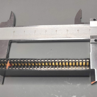
Trim the edges and insert the key. Don’t forget to glue the key, if you pull it out and don’t notice it, shorting the power and data lines will have a catastrophic consequences.
Assemble everything
This is not the only way on how to assemble this, it might not even be the easiest, but we started with soldering the EPM240T100C5N to the board. This is the hardest part in this assembly and the only reason this might not be a suitable project for a beginner. However if you’re doing this for the first time, be careful for chip orientation and that all of the legs are aligned with the pads.


Program the CPLD
CPLD programming resources that helped us a lot, since this was our first project with CPLD
If you’re using EPM240 or EMP7128 CPLD, you have already precompiled .pof files that you just need to upload to CPLD. Just don’t forget to power up the chip when doing so. If you’re using different CPLDs the project also contains the sources, so you may compile it on your own.
where to find the software for programing the CPLD (khm, back channels)


There is also available an alternative firmware and it can be found here. However this did not work at all for me. I have tried it on 2 different boards.
Add software to micro SD card
The micro SD card should contain the following software from:
TK-Pie-master\PI_SD
TK-Pie-master\PI_OS
folders so the at the end it should look like:

Final setup and usage

Simple enhancement
To add a reset functionality, just connect the RESET signal from the edge connector and GND. It’s a bit of a hack job, but it works.
Comparison between Tk-Pie and Composite
All of the following pictures, except the last one, are taken from my Samsung Smart TV, which has a weird post processing of composite input, so the results are not optimal to begin with and the difference is much bigger than the one taken on my friend’s monitor.
The picture from TK-Pie is obviously much more vivid and cleaner than the composite input, also no interference is present. There was no noticeable lag and even the games can be played quite well (I’m sure the purists will disagree).
However the improvement will also depend on TV/monitor you’re using. The composite picture on my friends monitor is much better than on my TV, so the difference is not as obvious.


This comparison is from my friends computer monitor/TV
Final thoughts
Assembling the device is a bit challenging for a beginner and even a seasoned electronic enthusiast will have some challenge with it, without the proper equipment, because of the 100 pin CPLD and SMD components.
Otherwise the device is quite straight-forward. However one thing that I would like to mention is that the TK-Pie is not quite consistent. There are some bugs in the firmware that sometimes do some erratic things .
But the biggest issue I personally had was that it did not work on its own, it only worked when connected via DivMMC EnJOY! PRO, why is something I was not able to figure out. It could be that my edge connector is damaged or some components might be slowly failing in my ZX 48k. If I find out what the reason is, I’ll update the article.
Second con that I noticed is that the TK-Pie could only be used for around 20 minutes before the ZX stopped to cooperate.

Due to the time delay I think that the TK-Pie is pushing the ZX to its limit and something might be overheating (maybe a voltage regulator or something else). This could be fixed by using an external power, however it would require a slight update to the design. Or maybe a simple firmware update and under-clocking the Raspberry Pi would do(I plan to test this theory and update the article).
Overall it was a fun and interesting little project and the design is working; however I think the project would benefit greatly from a bit of refining. In its current state I would not recommend it for everyday use.
Basic debug

The image on composite/RF was fine. The Raspberry Pi boots and works, however it’s not getting proper data from the TK-Pie.
Raspberry Pi Zero W
Ivan Goloskokovic (thank you for providing this!), managed to get the image to work on Pi Zero W by lowering arm_freq to 800 in the config.txt to:
disable_overscan=1


# Over clocking settings
arm_freq=800
core_freq=400
force_turbo=1
# Disable adjusting the refresh rate of RAM every 500 ms
disable_pvt=1
We presume that the Pi W uses too much power at native frequency.
Banana Pi Zero
To use alternative SBC like Banana Pi Zero (Allwinner H3 SoC which is armv7), you would need to recompile the source code, as the original precompiled image will work only on SoC arm1176jzf-s.
In order to recompile the code for other RPi or BPi you need to change base address at least
Here are some bare metal examples for RPi https://github.com/dwelch67/raspberrypi
but I don't see the point of using any other RPi than Zero because of the board format.
For BPi is even more difficult as it uses different addresses and documentation is non-existing. Having Allwinner H3 SoC it is possible to use Orange Pi documentation
but TK-Pie being a casual project with a small user base I don't see this effort available.
Thank you Ivan Goloskokovic, for providing this information.
NOTE: This has not been tested out, if you manage to make it work please let me know and I'll expand this section!
Resources and reviews:
Some videos to help you get the idea.
In Czech, use google translate:
HDMI výstup pro Sinclair ZX Spectrum - TK-Pie
Victor Trucco v rámci vývoje ZX Spectrum Next vymyslel HDMI výstup ze Speccy přes Raspberry Pi. Později od tohoto…
www.8bity.cz
TKPie HDMI interface by Piotr 'zaxon Bugaj
Sunday, March 19th, 2017 Since annoucment fro Victor Trucco of TKPie (also known as ZXPie) in 20.Oct 2016 and fast…
tooloudtoowide.marcinrusinowski.com
In Russian, use google translate:


shouldn't Pi Zero and Pi Zero W have the same image as they have the same CPU: -mcpu=arm1176jzf-s